01.D - Hello Constant Buffers

1 - Introduction
The sample we will review in this tutorial (D3D12HelloConstBuffers) makes use of a constant buffer to pass data from CPU to GPU (that is, from CPU system memory allocated and used by our C++ app to a GPU-visible heap), so that the shader programs can access the corresponding constant buffer data.
As you know, shaders receive input data from previous stages, but they can also access resources stored in GPU heaps with the assistance of root signatures. We delved into some of the theoretical aspects in a previous tutorial (01.B - Hello Triangle). Now, it’s time to put root signatures into practice. However, you might still be wondering why we need to transfer data from the CPU to the GPU. Well, there are several reasons for doing so. For instance, in this sample, we will transfer data to reposition a triangle over time. This enables us to simulate a simple animation, as illustrated in the image above.
2 - Constant buffers
Constant buffers are specially optimized for constant-variable usage, ensuring low-latency access and enabling frequent updates from the CPU. Consequently, they come with additional size, layout, and access restrictions. While the phrase “constant variables updated from the CPU” might seem contradictory, consider that even constant variables require initialization. In this context, “update” refers to the process of initializing a constant buffer with data that will remain constant throughout the execution of the shader programs that access it.
Each constant buffer can hold up to 4096 constants, where each constant comprises a maximum of four 32-bit values. Constant buffers must adhere to a 256-byte alignment constraint (meaning the starting address must be a multiple of 256). To fulfill this requirement, the simplest approach is to create constant buffers with sizes divisible by 256 bytes. This allows you to allocate space for an entire array of constant buffers on GPU heaps without concerns about alignment. In fact, CreateCommittedResource typically reserves memory space on GPU heaps with 4KB or 64KB alignment, which are both divisible by 256 bytes.
Declaring a constant buffer closely resembles declaring a structure in C\C++. However, unlike C\C++, we cannot allocate GPU memory space simply by defining a constant buffer instance within shader code. Constant buffers in HLSL can only be declared and referenced through their respective views. Typically, we first define a CPU version of the constant buffer (from our C++ application) to store temporary data during frame creation on the CPU timeline. Subsequently, we allocate sufficient GPU memory space on the upload heap to accommodate the constant buffer data. Then, this memory can be mapped to the virtual address space of our C++ application, given that the upload heap is CPU-visible memory. Therefore, we can use the CPU-side constant buffer (stored in system memory) as a source and the memory-mapped constant buffer as a destination for a copy operation to initialize the constant buffer on the upload heap. If the need arises to update the constant buffer data from the CPU timeline, we use a root signature to bind a view to the constant buffer on the upload heap. At that point, the shader code can access the constant buffer through the corresponding view bound to the slot (virtual register) associated with the declaration of the constant buffer in HLSL. As we will see in the next section, this is essentially what D3D12HelloConstBuffers does to both initialize and update the triangle position over time.
[!IMPORTANT]
When dealing with static constant buffer data, the common approach is to use the constant buffer residing on the upload heap as the source for a copy operation to update its counterpart on the default heap. This strategy enhances performance by allowing the GPU to directly access the constant buffer’s data stored in GPU memory, eliminating the need to incur PCI-e bus overhead in accessing it from system memory. We will delve into this topic in a subsequent tutorial.
3 - D3D12HelloConstBuffers: code review
Let’s start with the shader code.
cbuffer SceneConstantBuffer : register(b0)
{
    float4 offset;       // 4 x 4 = 16 bytes
    float4 padding[15];  // 15 x (4 x 4) = 240 bytes
};                       // Total = 256 bytes

struct PSInput
{
    float4 position : SV_POSITION;
    float4 color : COLOR;
};


PSInput VSMain(float4 position : POSITION, float4 color : COLOR)
{
    PSInput result;

    result.position = position + offset;
    result.color = color;

    return result;
}


float4 PSMain(PSInput input) : SV_TARGET
{
    return input.color;
}
In HLSL, the keyword cbuffer is used to declare a constant buffer, while register is employed to specify the virtual register (link name) where we aim to bind the corresponding constant buffer view. In this case, we intend to attach to slot 0 reserved for constant buffer views, thus we will bind to the virtual register b0. The first field of SceneConstantBuffer (the constant buffer defined in the above code) represents the offset we’ll use to translate the vertex positions. The second field is employed to pad the structure so that the constant buffer is 256 bytes in size and aligns to a 256-byte boundary.
[!NOTE]
In HLSL, you do not need to explicitly pad constant buffers to 256 bytes, as this is handled implicitly (it is minimum hardware allocation size). Moreover, observe that the scope and visibility of the fields within a constant buffer are extern to the structure, similar to enumerator constants in a C enumeration.
[!NOTE]
In this tutorial, we will bind the view that describes the constant buffer through a root table in the root signature. However, we could also have passed a CBV to a root descriptor, which is simply a GPU virtual addresses pointing to the associated resource. In both cases, no information regarding the data’s organization in memory is provided. This is why the definition of a constant buffer in HLSL is crucial for the GPU to access the related constant buffer data accurately.
Now, we can see the C++ code, starting from the application class.
class D3D12HelloConstBuffers : public DXSample
{
public:
    D3D12HelloConstBuffers(UINT width, UINT height, std::wstring name);

    virtual void OnInit();
    virtual void OnUpdate();
    virtual void OnRender();
    virtual void OnDestroy();

private:
    static const UINT FrameCount = 2;

    struct Vertex
    {
        XMFLOAT3 position;
        XMFLOAT4 color;
    };

    struct SceneConstantBuffer
    {
        XMFLOAT4 offset;
        float padding[60]; // Padding so the constant buffer is 256-byte aligned.
    };
    static_assert((sizeof(SceneConstantBuffer) % 256) == 0, "Constant Buffer size must be 256-byte aligned");

    // Pipeline objects.
    CD3DX12_VIEWPORT m_viewport;
    CD3DX12_RECT m_scissorRect;
    ComPtr<IDXGISwapChain3> m_swapChain;
    ComPtr<ID3D12Device> m_device;
    ComPtr<ID3D12Resource> m_renderTargets[FrameCount];
    ComPtr<ID3D12CommandAllocator> m_commandAllocator;
    ComPtr<ID3D12CommandQueue> m_commandQueue;
    ComPtr<ID3D12RootSignature> m_rootSignature;
    ComPtr<ID3D12DescriptorHeap> m_rtvHeap;
    ComPtr<ID3D12DescriptorHeap> m_cbvHeap;
    ComPtr<ID3D12PipelineState> m_pipelineState;
    ComPtr<ID3D12GraphicsCommandList> m_commandList;
    UINT m_rtvDescriptorSize;

    // App resources.
    ComPtr<ID3D12Resource> m_vertexBuffer;
    D3D12_VERTEX_BUFFER_VIEW m_vertexBufferView;
    ComPtr<ID3D12Resource> m_constantBuffer;
    SceneConstantBuffer m_constantBufferData;
    UINT8* m_pCbvDataBegin;

    // Synchronization objects.
    UINT m_frameIndex;
    HANDLE m_fenceEvent;
    ComPtr<ID3D12Fence> m_fence;
    UINT64 m_fenceValue;

    void LoadPipeline();
    void LoadAssets();
    void PopulateCommandList();
    void WaitForPreviousFrame();
};
We must define a structure similar to the constant buffer in the shader code as we need an instance where to store the results of our calculations on the constant buffer data that will be used to initialize\update the constant buffer on the upload heap. However, in this case we explicitly need to pad\extend the structure to 256 bytes as this is not handled automatically for us.
The transference of data between CPU memory and GPU heaps is a straightforward bit stream. This can pose a challenge as C++ and HLSL adhere to distinct rules for data packing. HLSL packs data into 4-byte boundaries, provided that it doesn’t cross a 16-byte boundary. As we know, a shader register is the basic unit to store data in shader cores. A shader register is composed of four 32-bit components (16 bytes in total). Now, consider having the following C++ structure definition:
struct S
{
    XMFLOAT3 mu;
    XMFLOAT2 mv;
    float mw;
};
and a similar definition in HLSL
cbuffer S
{
    float3 u;
    float2 v;
    float w;
};
In C++, we would have the following layout of data in memory for the S structure.
mu.x, mu.y, mu.z, mv.x, mv.y, mw.x
Since data transfer between CPU and GPU is a straightforward bit stream, the S structure would be loaded into shader registers in the following manner:
Register1: (mu.x, mu.y, mu.z, mv.x)
Register2: (mv.y, mw.x, empty, empty)
As you can see, the components of the vectors mu, mv and mw are packed into the 4-byte components of the two registers, but the field mv is split between them. However, the rules of HLSL state that data is packed so that it can’t cross a 16-byte boundary (that is, the size of a register). Therefore, we always must define C++ structures with the HLSL packing rules in mind. For example, a more suitable C++ definition for the S structure would be:
struct S
{
    XMFLOAT3 mu;
    float pack;
    XMFLOAT2 mv;
    float mw;
};
so that in HLSL we avoid splitting data between shader registers.
Register1: (mu.x, mu.y, mu.z, pack.x)
Register2: (mv.x, mv.y, mw.x, empty)
[!NOTE]
We can have more than a field\vector in the same shader register. Indeed, as you can see above, mv and mw are packed in the same shader register since they don’t cross its 16-byte boundary.
[!NOTE]
The HLSL packing rules also apply to both input and output parameters of the shader programs, with the exception of vertex shader input parameters. Since the input assembler cannot unpack data, it simply delivers each vertex attribute in a separate input register. This explains why we can use both float3 and float4 for the first parameter of VSMain (position), as pointed out in the previous tutorial. Indeed, either way, the next parameter (color) will be passed in the next input register. Nevertheless, this doesn’t fully explain why a float4 is required for the position field in the PSInput structure. We will revisit this in a later tutorial.
The constant buffer used by this sample (D3D12HelloConstBuffers) is a resource accessed by the vertex shader, so we need to specify it with a root parameter in a root signature. In this case, we will opt for a root table that includes a range of a single descriptor: a CBV (Constant Buffer View) that describes the constant buffer to the GPU. For this purpose, the application class introduces a fresh descriptor heap (m_cbvHeap) as we cannot repurpose m_rtvHeap, that holds the descriptors of the two render targets (recall that RTVs and CBVs may have different size, so they can’t share the same descriptor heap). Also, in the application class, you can find the following new private members:
m_constantBuffer is the object we can use from our C++ application to reference the constant buffer residing in the upload heap. We will use it to map the constant buffer to the virtual address space of our C++ application.
m_pCbvDataBegin is the starting virtual address where we will map the constant buffer (from the upload heap) in our C++ application.
m_constantBufferData is an instance of the constant buffer structure defined in the application class. It is where we will temporarily store the constant buffer data we will copy to the memory mapped constant buffer. This approach enables us to initialize the constant buffer on the upload heap since the physical memory that holds the constant buffer is the same.
Now, let’s take a brief look at the LoadPipeline function to see what’s new.
// Load the rendering pipeline dependencies.
void D3D12HelloConstBuffers::LoadPipeline()
{

    // ...


    // Create descriptor heaps.
    {
        // Describe and create a render target view (RTV) descriptor heap.
        D3D12_DESCRIPTOR_HEAP_DESC rtvHeapDesc = {};
        rtvHeapDesc.NumDescriptors = FrameCount;
        rtvHeapDesc.Type = D3D12_DESCRIPTOR_HEAP_TYPE_RTV;
        rtvHeapDesc.Flags = D3D12_DESCRIPTOR_HEAP_FLAG_NONE;
        ThrowIfFailed(m_device->CreateDescriptorHeap(&rtvHeapDesc, IID_PPV_ARGS(&m_rtvHeap)));

        m_rtvDescriptorSize = m_device->GetDescriptorHandleIncrementSize(D3D12_DESCRIPTOR_HEAP_TYPE_RTV);

        // Describe and create a constant buffer view (CBV) descriptor heap.
        // Flags indicate that this descriptor heap can be bound to the pipeline
        // and that descriptors contained in it can be referenced by a root table.
        D3D12_DESCRIPTOR_HEAP_DESC cbvHeapDesc = {};
        cbvHeapDesc.NumDescriptors = 1;
        cbvHeapDesc.Flags = D3D12_DESCRIPTOR_HEAP_FLAG_SHADER_VISIBLE;
        cbvHeapDesc.Type = D3D12_DESCRIPTOR_HEAP_TYPE_CBV_SRV_UAV;
        ThrowIfFailed(m_device->CreateDescriptorHeap(&cbvHeapDesc, IID_PPV_ARGS(&m_cbvHeap)));
    }


    // ...


}
Here, we create the two descriptor heaps we need in this sample: one for the two RTVs that describe the buffers in the swap chain and the other for the CBV that describes the constant buffer used by the vertex shader. Observe that we set the D3D12_DESCRIPTOR_HEAP_FLAG_SHADER_VISIBLE flag to specify that m_cbvHeap will be a shader-visible descriptor heap associated with the command list. This allows the GPU to access the related descriptors through a byte offset passed as a root argument to a root table in the root signature, as explained in tutorial 01.B - Hello Triangle.
[!NOTE]
Descriptor heaps created without specifying the flag D3D12_DESCRIPTOR_HEAP_FLAG_SHADER_VISIBLE allow applications the flexibility to stage descriptors in CPU system memory before copying them to a shader visible descriptor heap, as a convenience if required. However, it is perfectly acceptable for applications to directly create descriptors into shader-visible descriptor heaps, without the need for staging anything on the CPU side.
Now, we can review the code of the LoadAssets function.
// Load the sample assets.
void D3D12HelloConstBuffers::LoadAssets()
{
    // Create a root signature consisting of a descriptor table with a single CBV.
    {
        D3D12_FEATURE_DATA_ROOT_SIGNATURE featureData = {};

        // This is the highest version the sample supports. If CheckFeatureSupport succeeds, the HighestVersion returned will not be greater than this.
        featureData.HighestVersion = D3D_ROOT_SIGNATURE_VERSION_1_1;

        if (FAILED(m_device->CheckFeatureSupport(D3D12_FEATURE_ROOT_SIGNATURE, &featureData, sizeof(featureData))))
        {
            featureData.HighestVersion = D3D_ROOT_SIGNATURE_VERSION_1_0;
        }

        CD3DX12_DESCRIPTOR_RANGE1 ranges[1];
        CD3DX12_ROOT_PARAMETER1 rootParameters[1];

        ranges[0].Init(D3D12_DESCRIPTOR_RANGE_TYPE_CBV, 1, 0, 0, D3D12_DESCRIPTOR_RANGE_FLAG_DATA_STATIC);
        rootParameters[0].InitAsDescriptorTable(1, &ranges[0], D3D12_SHADER_VISIBILITY_VERTEX);

        // Allow input layout and deny uneccessary access to certain pipeline stages.
        D3D12_ROOT_SIGNATURE_FLAGS rootSignatureFlags =
            D3D12_ROOT_SIGNATURE_FLAG_ALLOW_INPUT_ASSEMBLER_INPUT_LAYOUT |
            D3D12_ROOT_SIGNATURE_FLAG_DENY_HULL_SHADER_ROOT_ACCESS |
            D3D12_ROOT_SIGNATURE_FLAG_DENY_DOMAIN_SHADER_ROOT_ACCESS |
            D3D12_ROOT_SIGNATURE_FLAG_DENY_GEOMETRY_SHADER_ROOT_ACCESS |
            D3D12_ROOT_SIGNATURE_FLAG_DENY_PIXEL_SHADER_ROOT_ACCESS;

        CD3DX12_VERSIONED_ROOT_SIGNATURE_DESC rootSignatureDesc;
        rootSignatureDesc.Init_1_1(_countof(rootParameters), rootParameters, 0, nullptr, rootSignatureFlags);

        ComPtr<ID3DBlob> signature;
        ComPtr<ID3DBlob> error;
        ThrowIfFailed(D3DX12SerializeVersionedRootSignature(&rootSignatureDesc, featureData.HighestVersion, &signature, &error));
        ThrowIfFailed(m_device->CreateRootSignature(0, signature->GetBufferPointer(), signature->GetBufferSize(), IID_PPV_ARGS(&m_rootSignature)));
    }

    // Create the pipeline state, which includes compiling and loading shaders.
    {

        // ...


        // Describe and create the graphics pipeline state object (PSO).
        D3D12_GRAPHICS_PIPELINE_STATE_DESC psoDesc = {};
        psoDesc.InputLayout = { inputElementDescs, _countof(inputElementDescs) };
        psoDesc.pRootSignature = m_rootSignature.Get();
        psoDesc.VS = CD3DX12_SHADER_BYTECODE(vertexShader.Get());
        psoDesc.PS = CD3DX12_SHADER_BYTECODE(pixelShader.Get());
        psoDesc.RasterizerState = CD3DX12_RASTERIZER_DESC(D3D12_DEFAULT);
        psoDesc.BlendState = CD3DX12_BLEND_DESC(D3D12_DEFAULT);
        psoDesc.DepthStencilState.DepthEnable = FALSE;
        psoDesc.DepthStencilState.StencilEnable = FALSE;
        psoDesc.SampleMask = UINT_MAX;
        psoDesc.PrimitiveTopologyType = D3D12_PRIMITIVE_TOPOLOGY_TYPE_TRIANGLE;
        psoDesc.NumRenderTargets = 1;
        psoDesc.RTVFormats[0] = DXGI_FORMAT_R8G8B8A8_UNORM;
        psoDesc.SampleDesc.Count = 1;

        ThrowIfFailed(m_device->CreateGraphicsPipelineState(&psoDesc, IID_PPV_ARGS(&m_pipelineState)));
    }

    // Create the command list.

    // ...


    // Create the vertex buffer.

    // ...


    // Create the constant buffer.
    {
        const UINT constantBufferSize = sizeof(SceneConstantBuffer);    // CB size is required to be 256-byte aligned.

        ThrowIfFailed(m_device->CreateCommittedResource(
            &CD3DX12_HEAP_PROPERTIES(D3D12_HEAP_TYPE_UPLOAD),
            D3D12_HEAP_FLAG_NONE,
            &CD3DX12_RESOURCE_DESC::Buffer(constantBufferSize),
            D3D12_RESOURCE_STATE_GENERIC_READ,
            nullptr,
            IID_PPV_ARGS(&m_constantBuffer)));

        // Describe and create a constant buffer view.
        D3D12_CONSTANT_BUFFER_VIEW_DESC cbvDesc = {};
        cbvDesc.BufferLocation = m_constantBuffer->GetGPUVirtualAddress();
        cbvDesc.SizeInBytes = constantBufferSize;
        m_device->CreateConstantBufferView(&cbvDesc, m_cbvHeap->GetCPUDescriptorHandleForHeapStart());

        // Map and initialize the constant buffer. We don't unmap this until the
        // app closes. Keeping things mapped for the lifetime of the resource is okay.
        CD3DX12_RANGE readRange(0, 0);        // We do not intend to read from this resource on the CPU.
        ThrowIfFailed(m_constantBuffer->Map(0, &readRange, reinterpret_cast<void**>(&m_pCbvDataBegin)));
        memcpy(m_pCbvDataBegin, &m_constantBufferData, sizeof(m_constantBufferData));
    }

    // Create synchronization objects and wait until assets have been uploaded to the GPU.

    // ...

}
We first check the highest root signature version available on the system (1.0 and 1.1 are the only versions available at the time of this writing). CheckFeatureSupport retrieves information about the features that are supported by the current graphics driver. The first parameter is a constant describing the feature(s) that we want to query for support. The second parameter is a pointer to a data structure whose type depends on the value passed as the first parameter. The second parameter is used both as an input and output parameter to pass\receive information to\from CheckFeatureSupport. The third parameter is the size of the structure passed in the second parameter.
Then, we create the root signature. The only root parameter is a descriptor table including a range of a single descriptor: the CBV that describes the constant buffer we are going to use in the vertex shader.
CD3DX12_DESCRIPTOR_RANGE1 is a helper structure to enable easy initialization of a D3D12_DESCRIPTOR_RANGE1 structure, which describes a descriptor range despite the root signature version used (that is, it allows to specify the volatility of both descriptors and data).
CD3DX12_ROOT_PARAMETER1 is a helper structure to enable easy initialization of a D3D12_ROOT_PARAMETER1 structure, which allow to describe a descriptor table despite the root signature version used (that is, as a collection of D3D12_DESCRIPTOR_RANGE1).
CD3DX12_VERSIONED_ROOT_SIGNATURE_DESC is a helper structure to enable easy initialization of a D3D12_VERSIONED_ROOT_SIGNATURE_DESC structure, which describe root signatures of any version (that is, root signatures that can hold root parameters of both D3D12_ROOT_PARAMETER and D3D12_ROOT_PARAMETER1).
CD3DX12_DESCRIPTOR_RANGE1::Init takes five parameters.
The first parameter specifies the type of descriptor range, while the second parameter indicates the number of descriptors in the range. In this case, we have a range with a single CBV.
The third parameter specifies the slot where we want to start binding the descriptors in the range. In this case, we specify 0, so that the only constant buffer view we have in the range will be bound to the virtual register b0.
The fourth parameter is the register space. This is nothing more than a way to help uniquely identify a bind point without overlapping with others. For now, you can simply pass 0. We’ll revisit register space in a subsequent tutorial.
The flag D3D12_DESCRIPTOR_RANGE_FLAG_DATA_STATIC specifies that both descriptors and data they reference are static. That is, once we set the root table as a root argument in the command list, we guarantee the driver that both the descriptors in the range and the data they reference won’t change until the GPU finishes the execution of the command list. This maximizes the potential for driver optimization.
CD3DX12_ROOT_PARAMETER1:: InitAsDescriptorTable takes the number of ranges in the descriptor table, the array of ranges and the shader visibility. This last parameter specifies which shaders need to access the root table. On some hardware, there can be a performance gain from only making descriptors visible to the shaders that actually require them.
During the creation of the root signature, we can pass a flag the specifies which shaders we want to deny access to the root signature. In this case, we deny access to most of the stages except the vertex shader, which needs to access the constant buffer view in the root signature. Denying access to shaders that don’t need the root signature to access resources can save the hardware some work. That is, for example, if the D3D12_SHADER_VISIBILITY_ALL flag has been set to broadcast the root parameters to all shader stages, denying access can overrule this and save the hardware some work. Additionally, if the shader is so simple that no resource accessible through the root signature is needed, then denying access can also be beneficial to optimize performance.
D3DX12SerializeVersionedRootSignature helps serialize a root signature of any version that can be passed to ID3D12Device::CreateRootSignature.
After creating the root signature, PSO, command list and vertex buffer, then we create the constant buffer.
First, we allocate memory space on the upload heap, as we need to update the constant buffer from the CPU timeline. Then, we use the GPU virtual address of the constant buffer and its size to create the related CBV, which will be stored in the first descriptor of m_cbvHeap.
We map the constant buffer to the virtual address space of our C++ application so that we can use the CPU memory-mapped version to initialize the constant buffer on the upload heap. As the comment states, keeping things mapped for the lifetime of the resource is okay. The resource will be automatically unmapped when we close the application. We use memcpy to copy the constant buffer data (m_constantBufferData) to the CPU memory-mapped constant buffer. This way, we initialize\update the constant buffer on the upload heap as well, since both are backed by the same physical memory. If you examine the complete code of D3D12HelloConstBuffers, you can see that m_constantBufferData is default initialized in the constructor of the application class, so the constant buffer fields will be all zero at first.
Now, let’s take a look at the PopulateCommandList function.
// Fill the command list with all the render commands and dependent state.
void D3D12HelloConstBuffers::PopulateCommandList()
{
    // Command list allocators can only be reset when the associated
    // command lists have finished execution on the GPU; apps should use
    // fences to determine GPU execution progress.
    ThrowIfFailed(m_commandAllocator->Reset());

    // However, when ExecuteCommandList() is called on a particular command
    // list, that command list can then be reset at any time and must be before
    // re-recording.
    ThrowIfFailed(m_commandList->Reset(m_commandAllocator.Get(), m_pipelineState.Get()));

    // Set necessary state.
    m_commandList->SetGraphicsRootSignature(m_rootSignature.Get());

    ID3D12DescriptorHeap* ppHeaps[] = { m_cbvHeap.Get() };
    m_commandList->SetDescriptorHeaps(_countof(ppHeaps), ppHeaps);

    m_commandList->SetGraphicsRootDescriptorTable(0, m_cbvHeap->GetGPUDescriptorHandleForHeapStart());
    m_commandList->RSSetViewports(1, &m_viewport);
    m_commandList->RSSetScissorRects(1, &m_scissorRect);

    // Indicate that the back buffer will be used as a render target.
    m_commandList->ResourceBarrier(1, &CD3DX12_RESOURCE_BARRIER::Transition(m_renderTargets[m_frameIndex].Get(), D3D12_RESOURCE_STATE_PRESENT, D3D12_RESOURCE_STATE_RENDER_TARGET));

    CD3DX12_CPU_DESCRIPTOR_HANDLE rtvHandle(m_rtvHeap->GetCPUDescriptorHandleForHeapStart(), m_frameIndex, m_rtvDescriptorSize);
    m_commandList->OMSetRenderTargets(1, &rtvHandle, FALSE, nullptr);

    // Record commands.
    const float clearColor[] = { 0.0f, 0.2f, 0.4f, 1.0f };
    m_commandList->ClearRenderTargetView(rtvHandle, clearColor, 0, nullptr);
    m_commandList->IASetPrimitiveTopology(D3D_PRIMITIVE_TOPOLOGY_TRIANGLELIST);
    m_commandList->IASetVertexBuffers(0, 1, &m_vertexBufferView);
    m_commandList->DrawInstanced(3, 1, 0, 0);

    // Indicate that the back buffer will now be used to present.
    m_commandList->ResourceBarrier(1, &CD3DX12_RESOURCE_BARRIER::Transition(m_renderTargets[m_frameIndex].Get(), D3D12_RESOURCE_STATE_RENDER_TARGET, D3D12_RESOURCE_STATE_PRESENT));

    ThrowIfFailed(m_commandList->Close());
}
ID3D12GraphicsCommandList::SetDescriptorHeaps changes the currently bound descriptor heaps that are associated with a command list. At any given time, no more than one combined CBV/SRV/UAV heap and one sampler heap can be bound. Whenever there is at least one shader that accesses a resource through a descriptor within a descriptor table’s range, the corresponding descriptor heap must be bound to the command list. In this case, we only set m_cbvHeap as the shader-visible descriptor heap, as we won’t be using dynamic samplers.
[!NOTE]
The descriptor table state is undefined at the beginning of a command list, as well as after changing the associated descriptor heaps. Once a descriptor heap is set for a command list, subsequent calls to define descriptor tables will reference the current descriptor heap.
By calling ID3D12GraphicsCommandList::SetGraphicsRootDescriptorTable, we set a descriptor table within the graphics root signature (that is, we pass a root table to a root parameter). The first parameter is the index of the root parameter in the root signature we want to set. The second parameter is a GPU handle (i.e., a byte offset) to the first descriptor within the first range among the ones included in the descriptor table.
[!NOTE]
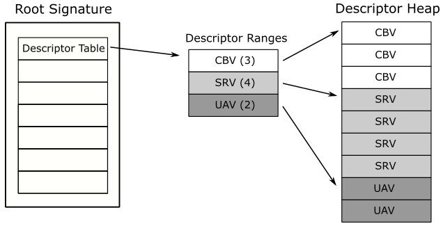
A descriptor table “knows” both the number of ranges and the number of descriptors each range contains. Therefore, we can simply pass a GPU handle to the first descriptor of the first range as second argument to SetGraphicsRootDescriptorTable. The only requirement is that the descriptors in each range of the descriptor table are contiguous in the descriptor heap (as shown in the figure below). While it is feasible to have non-contiguous ranges of descriptors, we’ll delve into this topic in a later tutorial.
At this point, when DrawInstanced is executed by the GPU, the vertex shader can read the constant buffer since the related view is bound to the slot b0, as specified in CD3DX12_ROOT_PARAMETER1:: InitAsDescriptorTable. However, there is a problem we need to solve: we initialized the members of the constant buffer to zero, so we won’t see any animation. Therefore, we need to constantly update the constant buffer data over time to see any effect on the screen. If you recall our discussion in the first tutorial (01.A - Hello Window), the window procedure keeps processing WM_PAINT messages sent directly to it, or posted to the message queue. That way, we can call both OnUpdate and OnRender in the WM_PAINT message handler to render updated geometries on the screen. Until now, the call to OnUpdate was a mere formality since it was an empty function. Now, we can finally implement and use it to modify the constant buffer data over time.
// Update frame-based values.
void D3D12HelloConstBuffers::OnUpdate()
{
    const float translationSpeed = 0.015f;
    const float offsetBounds = 1.25f;

    m_constantBufferData.offset.x += translationSpeed;
    if (m_constantBufferData.offset.x > offsetBounds)
    {
        m_constantBufferData.offset.x = -offsetBounds;
    }

    memcpy(m_pCbvDataBegin, &m_constantBufferData, sizeof(m_constantBufferData));
}
Here, we update the constant buffer data stored in the constant buffer variable (m_constantBufferData) declared in the application class. Then, we copy this data to the memory mapped constant buffer (m_pCbvDataBegin). This also updates the constant buffer on the upload heap (m_constantBuffer) as both are backed by the same physical memory.
[!NOTE]
As stated in the previous tutorial, a primitive is rendered on the screen as long as the x- and y-coordinates are in the range $[−1,\ 1]$. In OnUpdate we restrict both these coordinates in the interval $[−1.25,\ +1.25]$ so that the triangle exits one side and enter the other one without disappearing.
Source code: D3D12HelloWorld (DirectX-Graphics-Samples)
References
[1] DirectX graphics and gaming (Microsoft Docs)
[2] DirectX-Specs (Microsoft Docs)
If you found the content of this tutorial somewhat useful or interesting, please consider supporting this project by clicking on the Sponsor button. Whether a small tip, a one time donation, or a recurring payment, it’s all welcome! Thank you!
