01.A - Hello Window
1 - Introduction
DirectX provides a set of APIs that can be used to create games and graphics applications. Specifically, it includes support for high-performance 2-D and 3-D graphics, audio, arithmetic, and linear algebra operations. Below is a list of the main APIs included in DirectX. However, our primary focus is on Direct3D 12 and DirectXMath, the only ones we will be using for a while.
Direct3D provides functionality for performing 3-D graphics rendering tasks. It is used to draw primitives (i.e., points, lines, and triangles) within the rendering pipeline or to start parallel operations on the GPU. When we refer to Direct3D 12, we are specifically talking about the API that enables apps to leverage the graphics and computing capabilities of PCs equipped with a DirectX 12-compatible GPU.
Direct2D offers functionality for rendering 2-D geometries, bitmaps, and text. It is designed to interoperate with existing code that uses Direct3D to create 2D menus, user interface (UI) elements, and Heads-up Displays (HUDs).
DirectWrite provides support for high-quality text rendering, resolution-independent outline fonts, and full Unicode text and layouts. It is designed to interoperate with Direct2D to render text by taking advantage of hardware acceleration. Text can also be filled with an arbitrary Direct2D brush, such as radial gradients, linear gradients, and bitmaps.
DirectXMath provides types and helper functions for common linear algebra and graphics math operations that are frequently used in DirectX applications.
XAudio2 allows the addition of sound effects and background music, or the development of high-performance audio engines.
XInput enables applications to receive input from the Xbox Controller when it is connected to a Windows PC.
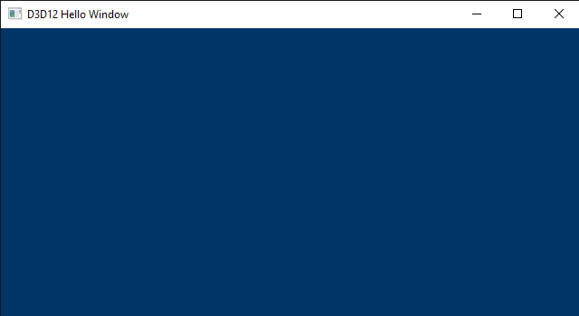
To create graphics applications, you first need a window to draw on. Therefore, the aim of this tutorial is to create and display a simple window on your screen. For this purpose, we will examine the sample D3D12HelloWindow. The related source code can be found in the official Microsoft repository (the link is provided at the end of the tutorial). The only significant graphics operation performed by this sample is the setting of the window background color. You might be surprised to discover that you need to write a substantial amount of code to execute this simple operation. The good news is that the code we will review in this first tutorial primarily consists of boilerplate code. This means that, by the end of this tutorial, you will have a basic understanding of the common framework used by almost all samples we will examine in the upcoming tutorials, so we can solely focus on new additions.
Before starting to review the source code of the sample D3D12HelloWindow, you need a basic understanding of the Component Object Model (COM), the DXGI API, as well as how Windows applications work. You can skip the following three sections if you are comfortable with these topics. Alternatively, you can also refer to [1]-[3] for further information.
2 - Windows applications
This section is heavily inspired by the first chapter of the book “Programming Microsoft Visual C++, Fifth Edition” by David J. Kruglinski, George Shepherd and Scott Wingo.
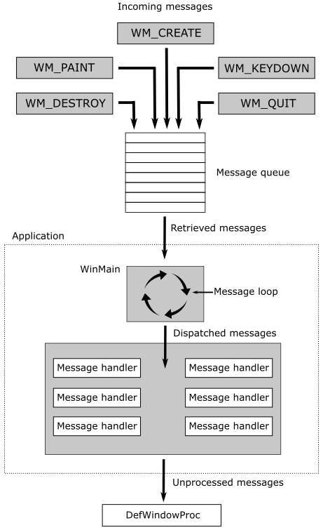
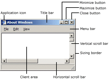
Windows applications use an event-driven programming model, as illustrated in the following below. In this model, programs respond to events by processing messages sent by the operating system. An event could be a keystroke, a mouse click, or a command for a window to repaint itself. The entry point of a Windows application is a function called WinMain, but most of the action occurs in a function known as the window procedure. The window procedure processes messages sent by the OS to the application that a window belongs to. WinMain creates that window and then enters a message loop, retrieving messages and dispatching them to the window procedure. Messages wait in a message queue until they are retrieved. The primary task of a Windows application is to respond to the messages it receives. In between messages, it does little except wait for the next message to arrive. An application can exit the message loop when a WM_QUIT message is retrieved from the message queue, signaling that the application is about to end. This message is sent by the OS when the user closes the window. When the message loop ends, WinMain returns, and the application terminates.
Note that window messages can also be sent directly to a window procedure, bypassing the message queue. If the sending thread is dispatching a message to a window created by the same thread, the window procedure of the specified window is invoked. However, if a thread is dispatching a message to a window created by a different thread, the process becomes more complex. Fortunately, we don’t need to delve into the low-level details in this tutorial series.
2.1 - Window Procedure
As previously mentioned, a window procedure is a function that receives and processes messages sent by the operating system to the application that a window belongs to. A window class defines key characteristics of a window, such as its window procedure address, its default background color, and its icon. Every window created with a specific class will use the same window procedure to respond to messages.
When the application dispatches a message to a window procedure, it also passes additional information about the message as arguments in its input parameters. This allows the window procedure to perform an appropriate action for a message by consuming the related message data. If a window procedure does not process a message, it must return the message to the system for default processing by calling the DefWindowProc function, which performs a default action and returns a message result. The window procedure must then return this value as its own message result.
Since a window procedure is shared by all windows belonging to the same class, it can process messages for different windows. To identify the specific window a message is addressed to, a window procedure can examine the window handle passed as an input parameter. The code provided in the window procedure to process a particular message is known as a message handler.
2.2 - Messages
Windows defines many different message types. Usually, messages have names that begin with the letters “WM_”, as in WM_CREATE and WM_PAINT. The following table shows ten of the most common messages.
| Message | Sent when |
|---|---|
| WM_CHAR | A character is input from the keyboard. |
| WM_COMMAND | The user selects a menu item, or a control sends a notification to its parent. |
| WM_CREATE | A window is created. |
| WM_DESTROY | A window is destroyed. |
| WM_LBUTTONDOWN | The left mouse button is pressed. |
| WM_LBUTTONUP | The left mouse button is released. |
| WM_MOUSEMOVE | The mouse pointer is moved. |
| WM_PAINT | A window needs repainting. |
| WM_QUIT | The application is about to terminate. |
| WM_SIZE | A window is resized. |
For example, a window receives a WM_PAINT message when its interior needs repainting. You can think of a Windows program as a collection of message handlers.
When the message loop dispatches a message, the window procedure is called, and you can retrieve the information on the message from its four input parameters:
-
The handle of the window to which the message is directed,
-
A message ID, and
-
Two 32-bit parameters known as wParam and lParam.
The window handle is a 32-bit value that uniquely identifies a window. Internally, the value references a data structure in which the OS stores relevant information about the window such as its size, style, and location on the screen.
The message ID is a numeric value that identifies the message type: WM_CREATE, WM_PAINT, and so on.
wParam and lParam contain information specific to the message type. For example, when a WM_LBUTTONDOWN message arrives, wParam holds a series of bit flags identifying the state of the Ctrl and Shift keys and of the mouse buttons. lParam holds two 16-bit values identifying the location of the mouse pointer (in screen coordinates) when the click occurred. At that point, you have all you need to know to process the WM_LBUTTONDOWN message in the window procedure. Conventionally, WinMain should return the value stored in the wParam of the WM_QUIT message.
The only criticism to the above explanation is that, unlike typical window applications, graphics applications perform the majority of their processing in between messages. However, D3D12HelloWindow is an exception as its sole purpose is to display a window on the screen (i.e., no significant graphics operations are involved).
3 - Component Object Model (COM)
Microsoft used the Component Object Model (COM) to design the internals of DirectX. Therefore, whenever you program with DirectX, you are also implicitly using COM. This is an object-oriented programming model created by Microsoft to break dependencies of the code at the binary level. This implies that if an API, a framework, or a generic technology is built upon COM, then it will be language-independent and backward-compatible, to a certain extent.
[!NOTE]
Unfortunately, this doesn’t automatically mean you can write DirectX applications using any programming language you want, or that you can run a DX12 application with older libraries and runtime (DX11 or earlier).
COM is a complex programming model, but fortunately, you don’t need to master it to write DirectX applications. Indeed, we will only use COM as end-users rather than for developing our API or framework. That is, DirectX will hide the complexity of COM from us. However, to effectively program with DirectX, we still need to know some basic concepts about COM. First, it can be useful to understand what it means to break dependencies of the code at the binary level and what type of problems this break can solve.
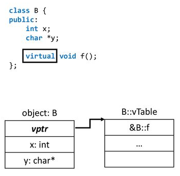
If you’ve ever developed a Windows library, you’re likely familiar with the process of exporting functionality from DLLs written in the C language for use by applications written in other languages (such as C++, C#, Java, Python, etc.). Microsoft didn’t use C to write DirectX, though. They preferred an object-oriented language like C++. Now, consider the scenario of writing a DLL that exports a C++ class. The functionality provided by this class can’t be easily used by other languages because C++ only specifies what happens at the source code level. The standard doesn’t say anything about what happens at the binary level. For example, we know that object-oriented languages use virtual tables to implement polymorphism. However, this is an implementation concept, just like the stack and the heap: the C++ standard doesn’t say anything about how to implement polymorphism. The following image shows a common layout for a class in memory. However, nothing prevents a new language from placing the virtual table pointer at the end, or defining a whole new system to implement polymorphism.
In other words, using a C++ class exported from a DLL is feasible as long as you are operating on the same OS and with the same compiler. Conversely, other languages or different implementations of C++ might struggle to communicate with the DLL if they lack knowledge about the binary layout of the exported class in memory. Specifically, when a compiler attempts to resolve a call to a virtual function, it requires knowledge of the class’s memory layout to access the function in the virtual table.
Even if you were able to use a C++ class exported from a DLL, one problem still remains. Typically, the DLL developer provides an include file with the class declaration. Now, consider using this include file to compile an application that creates an instance of the exported class as a local variable on the stack. Additionally, assume you place the DLL in the executable directory of your application. Also, suppose that you put the DLL in the executable directory of your application. After a while, the developer releases an updated version of their DLL, and you choose to overwrite the old one in the executable directory without recompiling your app as the notes of the developer indicate they only added a private member in the exported class. Indeed, C++ rules state that everything should be fine as the public part has not changed. The problem is that this statement is only valid at the source level, not at the binary level. If you now execute your app, the new DLL is loaded in memory and the new constructor of the exported class is invoked to initialize the new private member. However, you haven’t recompiled your app, so the space reserved for the local variable on the stack is the one specified by the definition of the class in the old include file you used to compile the first time. You can easily imagine how this can lead to incorrect results, or even worse, crashes.
These problems arise from the fact that the binary representation of the DLL is exposed to the app. COM try to resolve this inconvenience with few fundamental principles:
-
Clients (apps) communicate with servers (DLLs) using abstract interfaces instead of concrete classes. If a server exports a class (called COM class) that implements an interface, a client can reference an instance of the COM class (called COM object) through an interface pointer and use it to call the member methods exported by the COM class.
-
Clients create COM objects using methods implemented in the servers. That way, the implementation of the COM class is hidden from the clients entirely. Only the server knows how to create a COM object, so if the private part of the COM class changes, the client is not affected because the interface is still the same — interfaces don’t contain data members.
-
COM classes and interfaces have unique IDs. That way it’s possible for more than a server to implement the same interface, and for a client to load the correct server (DLL) in memory. So, if there are more versions of the DLL available, the client can choose what server to load. Then, if your application wants to use new functionalities, you are forced to recompile.
However, even though COM involves the use of abstract interfaces, client and server still need to agree on the binary representation of these interfaces for effective communication. To address this, the COM specification outlines a binary object layout that can be implemented and comprehended by nearly any language and platform. Notably, Microsoft opted to employ a virtual table mechanism similar to the one used in their C++ implementation. Essentially, a COM interface in memory is nothing more than a virtual table containing function pointers and additional data. Consequently, an interface pointer to a COM object is merely a pointer to a virtual table.
In essence, for a language or compiler to support COM, it must adhere to the layout of COM interfaces as specified by the COM specification. This requirement highlights one of the reasons why you may not always be able to use DirectX with your preferred programming language.
As mentioned earlier, clients cannot directly create COM objects. Typically, we use a method like CoCreateInstance, specifying the COM class ID for which the client wants to create a COM object, and the interface ID implemented by the COM class that the client is interested in obtaining a pointer to. The client doesn’t need to know where the server is located. The Windows Registry is used for this purpose, and CoCreateInstance (with the help of a system service) can locate the server based on the arguments passed as parameters. At this point, the server can create the COM object, and an interface pointer to that object is returned to the client, which can use it to communicate with the server (i.e., call its member functions).
However, you would rarely use CoCreateInstance to directly create DirectX COM objects. Typically, we will create COM objects indirectly by using specific DirectX methods that return pointers (as output parameters) to whatever interface is implemented by the related COM classes. Although this mechanism is less centralized (i.e., it doesn’t rely on the Windows Registry to locate servers), it functions similarly. Generally, the functions to create DirectX COM objects return an HRESULT, an encoded value indicating the success or failure of the operation.
At this point we can better define the meaning of backward compatibility mentioned at the beginning of this section. In short, a DirectX application can run on a system provided that the servers with the COM classes used by the client can be loaded. So, as long as new versions of a DLL don’t change the COM classes to include new disruptive functionalities that modify the related COM interfaces, the application can still load the new DLL and use the new COM classes without problems.
before creating any COM object, you should initialize the COM library by calling CoInitializeEx. However, when you create COM objects indirectly, the creation methods will handle this task for you. We will see many examples of such methods in the upcoming tutorials.
COM defines a base interface that all other interfaces must extend: IUnknown. This interface defines some basic operations:
-
AddRef increments the reference count for an interface pointer to a COM object. You should call this method whenever you make a copy of an interface pointer.
-
Release decrements the reference count for an interface on a COM object. When the reference count on an object reaches zero, this method must cause the interface pointer to free itself.
-
QueryInterface queries a COM object for a pointer to one of its interfaces; identifying the interface by a reference to its interface identifier (IID). If the COM object implements the interface, then it returns a pointer to that interface after calling AddRef on it.
Directly managing interface pointers to COM objects can be a challenging task, as you need to explicitly call Release and AddRef to maintain the reference count. A more convenient solution with C++ is to use smart pointers. Microsoft::WRL::ComPtr is a smart pointer provided by the Windows Runtime C++ Template Library (WRL). This library is “pure” C++, making it suitable for classic Win32 desktop applications. It automatically calls AddRef and Release on the underlying interface pointer, meaning it maintains a reference count for the underlying interface pointer and releases the interface pointer when the reference count drops to zero. Moreover, it defines various other methods, including:
-
Get returns the underlying interface pointer to a COM object. It’s especially useful when you have functions that accept a raw interface pointer instead of a ComPtr.
-
GetAddressOf returns a pointer to the underlying interface pointer to a COM object. It’s especially useful because, whenever you create a COM object indirectly, the default is to return the interface pointer as an output parameter (i.e., as a pointer to an interface pointer).
-
Reset calls Release on the underlying interface pointer to a COM object and then set it to nullptr. It can be useful when you don’t need the underlying interface pointer anymore, but the ComPtr hasn’t gone out of scope yet.
-
ReleaseAndGetAddressOf is similar to Reset but it returns the underlying pointer (that will be a nullptr) to the caller. It can be useful if you want a new initialization for an underlying interface pointer you don’t need anymore (e.g., when you want to pass it as an argument to the output parameter of a creation method).
-
Detach returns the underlying interface pointer to a COM object and then set it to nullptr. It can be useful if you need to return the underlying interface pointer to a caller and, at the same time, you don’t need the local ComPtr object anymore.
-
As is just a wrapper around QueryInterface. It takes another ComPtr as input parameter to get a pointer to one of the interfaces implemented by a COM object.
Also, the dereference operator -> is overloaded and returns the underlying interface pointer to a COM object, so that you don’t need to call Get if you only want to invoke a function through the interface pointer.
4 - DirectX Graphics Infrastructure (DXGI)
Microsoft DirectX Graphics Infrastructure (DXGI) is an API that collects functionality and tasks that don’t change regardless of the version of graphics API you are actually using (Direct3D 10, 11, or 12). Specifically, DXGI manages low-level tasks such as enumerating hardware graphics devices (GPUs) and outputs (monitors), creating rendering buffers, presenting rendered frames to an output, controlling gamma, and managing full-screen transitions. This allows a graphics API to focus on drawing 3D content into buffers without worrying about the origin of these buffers or how they will be displayed.
DXGI’s purpose is to communicate with the kernel mode driver and the system hardware, as shown in the following diagram.
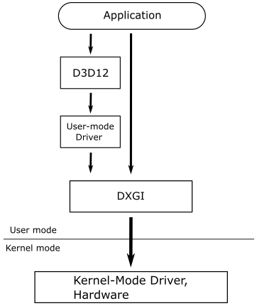
A graphics application can either access DXGI directly or use the Direct3D API, which manages communications with DXGI. You might prefer to interact with DXGI directly if your application needs to enumerate devices or control how data is presented to an output.
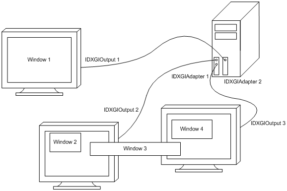
An adapter is an abstraction of a hardware or software device. Typically, there are multiple adapters on a machine. Some devices are implemented in hardware, such as a video card, while others are implemented in software, like the Direct3D rasterizer provided by Microsoft. The following diagram illustrates a system with a single computer, two adapters (video cards), and three output monitors.
The primary task of your graphics applications is to draw on buffers and ask DXGI to present those buffers as frames to the output. If the application has two buffers available, it can render on one buffer (the render target) while presenting another one. Depending on the time it takes to render a frame, or the desired frame rate for presentation, the application may need more than two buffers. The collection of buffers created is referred to as a swap chain, as depicted in the following illustration.
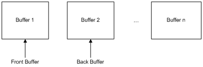
A swap chain consists of one front (or present) buffer and one or more back buffers, which are used as render targets. Each application creates its own swap chain. To maximize the speed of data presentation to an output, a swap chain is almost always created in GPU memory. DXGI, with the assistance of the kernel driver, is responsible for scanning rendered content in the front buffer from video memory and presenting it on outputs.
A swap chain can be configured for drawing in either full-screen or windowed mode, eliminating the need to determine whether an output is windowed or full screen. A full-screen mode swap chain can optimize performance by switching the display resolution. An output can support one or more display modes, which include resolution, refresh rate, format, etc. DXGI might change the display mode of an output when making a full-screen transition. However, resizing swap chain buffers will not trigger a display mode switch. The swap chain makes an implicit promise that if you choose a back buffer that exactly matches a display mode supported by the target output, then it will switch to that display mode when entering full-screen mode on that output. Consequently, you actually select a display mode by choosing your back buffer size and format.
5 - Framework overview
As stated at the beginning of this tutorial, the framework used by D3D12HelloWindow is common to almost all the samples we will review in the upcoming tutorials. This means that by the end of this tutorial, you will know how to write a generic DirectX application, or at least the backbone of a complete graphics application.
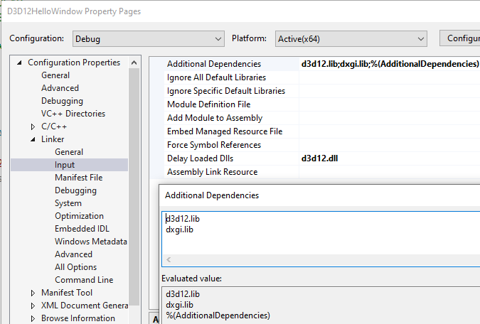
Firstly, as you can see in the following image, the import libraries (LIBs) of Direct3D 12 and DXGI are listed in the additional dependencies of the project. This allows the linker to use the related information to resolve external references to exported functions in the corresponding DLLs. Additionally, the DLL associated with Direct3D 12 will not be loaded at the same time as the application, but only the first time we call an exported function.
DirectX applications are normal Windows programs, so the entry point is WinMain as usual.
#include "stdafx.h"
#include "D3D12HelloWindow.h"

_Use_decl_annotations_
int WINAPI WinMain(HINSTANCE hInstance, HINSTANCE, LPSTR, int nCmdShow)
{
    D3D12HelloWindow sample(1280, 720, L"D3D12 Hello Window");
    return Win32Application::Run(&sample, hInstance, nCmdShow);
}
[!NOTE]
Use_decl_annotations is a macro that simplifies SAL annotations. We won’t go into detail about this concept, as it’s not relevant for this tutorial or the rest of the series. If you want to learn more, check out the official Microsoft documentation (by searching for “Using SAL Annotations”).
The header file stdafx.h includes others header files associated with various DirectX libraries (Direct3D 12, DirectXMath, DXGI). We need to include wrl.h to use the smart pointers provided by the Windows Template Library. The header file d3dx12.h defines many helper structures used as C++ wrapper classes around Direct3D 12 native structures to simplify their initialization (it also provides some helper functions to make it easier to handle subresources). D3DCompiler.h is the header associated with a library we will use to compile shader code. The concepts of subresources and shader code will be explored in upcoming tutorials.
#include <windows.h>

#include <d3d12.h>
#include <dxgi1_6.h>
#include <D3Dcompiler.h>
#include <DirectXMath.h>
#include "d3dx12.h"

#include <string>
#include <wrl.h>
#include <shellapi.h>
WinMain is called by the C/C++ runtime startup and takes four parameters. However, we are only interested in two of them (the named ones in the code illustrated above).
hInstance is the base virtual address of the executable loaded in memory.
nCmdShow is an integer value that controls how to show the window we are going to create. We’ll pass this last parameter to a function whose primary purpose is to show the window of our sample (more on this in the next section).
D3D12HelloWindow is the application class, which defines data and methods specific to the sample.
class D3D12HelloWindow : public DXSample
{
public:
    D3D12HelloWindow(UINT width, UINT height, std::wstring name);

    virtual void OnInit();
    virtual void OnUpdate();
    virtual void OnRender();
    virtual void OnDestroy();

private:
    static const UINT FrameCount = 2;

    // Pipeline objects.
    ComPtr<IDXGISwapChain3> m_swapChain;
    ComPtr<ID3D12Device> m_device;
    ComPtr<ID3D12Resource> m_renderTargets[FrameCount];
    ComPtr<ID3D12CommandAllocator> m_commandAllocator;
    ComPtr<ID3D12CommandQueue> m_commandQueue;
    ComPtr<ID3D12DescriptorHeap> m_rtvHeap;
    ComPtr<ID3D12PipelineState> m_pipelineState;
    ComPtr<ID3D12GraphicsCommandList> m_commandList;
    UINT m_rtvDescriptorSize;

    // Synchronization objects.
    UINT m_frameIndex;
    HANDLE m_fenceEvent;
    ComPtr<ID3D12Fence> m_fence;
    UINT64 m_fenceValue;

    void LoadPipeline();
    void LoadAssets();
    void PopulateCommandList();
    void WaitForPreviousFrame();
};
The base class DXSample defines data and methods used by all graphics samples.
class DXSample
{
public:
    DXSample(UINT width, UINT height, std::wstring name);
    virtual ~DXSample();

    virtual void OnInit() = 0;
    virtual void OnUpdate() = 0;
    virtual void OnRender() = 0;
    virtual void OnDestroy() = 0;

    // Samples override the event handlers to handle specific messages.
    virtual void OnKeyDown(UINT8 /*key*/)   {}
    virtual void OnKeyUp(UINT8 /*key*/)     {}

    // Accessors.
    UINT GetWidth() const           { return m_width; }
    UINT GetHeight() const          { return m_height; }
    const WCHAR* GetTitle() const   { return m_title.c_str(); }

    void ParseCommandLineArgs(_In_reads_(argc) WCHAR* argv[], int argc);

protected:
    std::wstring GetAssetFullPath(LPCWSTR assetName);

    void GetHardwareAdapter(
        _In_ IDXGIFactory1* pFactory,
        _Outptr_result_maybenull_ IDXGIAdapter1** ppAdapter,
        bool requestHighPerformanceAdapter = false);

    void SetCustomWindowText(LPCWSTR text);

    // Viewport dimensions.
    UINT m_width;
    UINT m_height;
    float m_aspectRatio;

    // Adapter info.
    bool m_useWarpDevice;

private:
    // Root assets path.
    std::wstring m_assetsPath;

    // Window title.
    std::wstring m_title;
};
The class Win32Application defines data and methods used by all Windows applications.
class Win32Application
{
public:
    static int Run(DXSample* pSample, HINSTANCE hInstance, int nCmdShow);
    static HWND GetHwnd() { return m_hwnd; }

protected:
    static LRESULT CALLBACK WindowProc(HWND hWnd, UINT message, WPARAM wParam, LPARAM lParam);

private:
    static HWND m_hwnd;
};
It’s perfectly fine if you don’t understand the meaning of every single class member. I’ll explain each of them in the next section and in later tutorials.
As you might have noticed in the first listing of this section, the entry point WinMain calls the constructor of D3D12HelloWindow.
D3D12HelloWindow::D3D12HelloWindow(UINT width, UINT height, std::wstring name) :
    DXSample(width, height, name),
    m_frameIndex(0),
    m_rtvDescriptorSize(0)
{
}
This constructor initializes some data members to zero and calls the constructor of the base class (DXSample).
DXSample::DXSample(UINT width, UINT height, std::wstring name) :
    m_width(width),
    m_height(height),
    m_title(name),
    m_useWarpDevice(false)
{
    WCHAR assetsPath[512];
    GetAssetsPath(assetsPath, _countof(assetsPath));
    m_assetsPath = assetsPath;

    m_aspectRatio = static_cast<float>(width) / static_cast<float>(height);
}
Here, we initialize the name of our graphics sample (to be shown in the title bar), as well as the width and height of the window’s client area on which we are going to draw.
GetAssetsPath returns the absolute path of the executable. This is where the application will locate the resource files (shaders, textures, etc.) needed to run the sample. However, we don’t need these types of resources for this first sample, so you won’t find anything in the executable directory, except for the executable itself, of course.
The aspect ratio refers to the proportional relationship between the width and height of the window’s client area.
The client area of a window is where we are allowed to draw. Technically speaking, it’s the area where the render target will be mapped once the GPU has completed drawing a frame on it. You can typically think of a render target as a texture that the GPU uses for rendering or drawing purposes.
Then, in WinMain, Win32Application::Run is invoked passing the instance of D3D12HelloWindow just created and the arguments for the named parameter of WinMain.
int Win32Application::Run(DXSample* pSample, HINSTANCE hInstance, int nCmdShow)
{
    // Parse the command line parameters
    int argc;
    LPWSTR* argv = CommandLineToArgvW(GetCommandLineW(), &argc);
    pSample->ParseCommandLineArgs(argv, argc);
    LocalFree(argv);

    // Initialize the window class.
    WNDCLASSEX windowClass = { 0 };
    windowClass.cbSize = sizeof(WNDCLASSEX);
    windowClass.style = CS_HREDRAW | CS_VREDRAW;
    windowClass.lpfnWndProc = WindowProc;
    windowClass.hInstance = hInstance;
    windowClass.hCursor = LoadCursor(NULL, IDC_ARROW);
    windowClass.lpszClassName = L"DXSampleClass";
    RegisterClassEx(&windowClass);

    RECT windowRect = { 0, 0, static_cast<LONG>(pSample->GetWidth()), static_cast<LONG>(pSample->GetHeight()) };
    AdjustWindowRect(&windowRect, WS_OVERLAPPEDWINDOW, FALSE);

    // Create the window and store a handle to it.
    m_hwnd = CreateWindow(
        windowClass.lpszClassName,
        pSample->GetTitle(),
        WS_OVERLAPPEDWINDOW,
        CW_USEDEFAULT,
        CW_USEDEFAULT,
        windowRect.right - windowRect.left,
        windowRect.bottom - windowRect.top,
        nullptr,        // We have no parent window.
        nullptr,        // We aren't using menus.
        hInstance,
        pSample);

    // Initialize the sample. OnInit is defined in each child-implementation of DXSample.
    pSample->OnInit();

    ShowWindow(m_hwnd, nCmdShow);

    // Main sample loop.
    MSG msg = {};
    while (msg.message != WM_QUIT)
    {
        // Process any messages in the queue.
        if (PeekMessage(&msg, NULL, 0, 0, PM_REMOVE))
        {
            TranslateMessage(&msg);
            DispatchMessage(&msg);
        }
    }

    pSample->OnDestroy();

    // Return this part of the WM_QUIT message to Windows.
    return static_cast<char>(msg.wParam);
}
To create a window, we first need an instance of a window class (represented by the WNDCLASSEX structure) to specify some basic information about all the windows created using that instance. Below is a list of the most important fields of WNDCLASSEX.
style specifies some additional information about the window. CS_HREDRAW | CS_VREDRAW indicates to redraw the entire window if a size adjustment changes the width and\or height of the client area.
hCursor specifies the cursor showed when this is over the window’s client area.
hInstance specifies the application a window belongs to. This information is passed as an argument to the first parameter of WinMain.
lpszClassName specifies the name we want to give to the window class.
lpfnWndProc specifies the address of the window procedure.
RegisterClassEx registers the window class, so we can use an instance of this class to create one or more windows with a specific style, window procedure, etc.
CreateWindow, as the name suggests, creates a window and returns its handle. It takes the name of a window class and some additional information as parameters. Look at the Microsoft documentation for more details on CreateWindow.
[!NOTE]
The instance of the application class, which is passed as an argument to the first parameter of Run, stores the width and height of the window’s client area. However, CreateWindow requires the size of the entire window, so we must calculate it. AdjustWindowRect provides this information if you pass the size of the client area and the style of the window you’re going to create with CreateWindow. WS_OVERLAPPEDWINDOW specifies a window with a title bar and no menu.
[!NOTE]
With the last parameter of CreateWindow, we can specify a pointer that the OS will return to us in response to a WM_CREATE message. This message is sent by the OS to an application as soon as a window is created, i.e., when CreateWindow returns. This allows us to save the instance of DXSample for later access (more on this shortly).
Observe how the OnInit method is called through the pSample pointer (an instance of the DXSample class) before showing the window on the screen to the user.
6 - D3D12HelloWindow: code review
DXSample::OnInit is a virtual function that needs to be redefined in derived classes. Indeed, we have done so in the definition of the application class (D3D12HelloWindow). The related implementation can be seen below.
void D3D12HelloWindow::OnInit()
{
    LoadPipeline();
    LoadAssets();
}
It simply calls the LoadPipeline and LoadAssets functions. Let’s start with LoadPipeline.
// Load the rendering pipeline dependencies.
void D3D12HelloWindow::LoadPipeline()
{
    UINT dxgiFactoryFlags = 0;

#if defined(_DEBUG)
    // Enable the debug layer (requires the Graphics Tools "optional feature").
    // NOTE: Enabling the debug layer after device creation will invalidate the active device.
    {
        ComPtr<ID3D12Debug> debugController;
        if (SUCCEEDED(D3D12GetDebugInterface(IID_PPV_ARGS(&debugController))))
        {
            debugController->EnableDebugLayer();

            // Enable additional debug layers.
            dxgiFactoryFlags |= DXGI_CREATE_FACTORY_DEBUG;
        }
    }
#endif

    ComPtr<IDXGIFactory4> factory;
    ThrowIfFailed(CreateDXGIFactory2(dxgiFactoryFlags, IID_PPV_ARGS(&factory)));

    if (m_useWarpDevice)
    {
        ComPtr<IDXGIAdapter> warpAdapter;
        ThrowIfFailed(factory->EnumWarpAdapter(IID_PPV_ARGS(&warpAdapter)));

        ThrowIfFailed(D3D12CreateDevice(
            warpAdapter.Get(),
            D3D_FEATURE_LEVEL_11_0,
            IID_PPV_ARGS(&m_device)
            ));
    }
    else
    {
        ComPtr<IDXGIAdapter1> hardwareAdapter;
        GetHardwareAdapter(factory.Get(), &hardwareAdapter);

        ThrowIfFailed(D3D12CreateDevice(
            hardwareAdapter.Get(),
            D3D_FEATURE_LEVEL_11_0,
            IID_PPV_ARGS(&m_device)
            ));
    }

    // Describe and create the command queue.
    D3D12_COMMAND_QUEUE_DESC queueDesc = {};
    queueDesc.Flags = D3D12_COMMAND_QUEUE_FLAG_NONE;
    queueDesc.Type = D3D12_COMMAND_LIST_TYPE_DIRECT;

    ThrowIfFailed(m_device->CreateCommandQueue(&queueDesc, IID_PPV_ARGS(&m_commandQueue)));

    // Describe and create the swap chain.
    DXGI_SWAP_CHAIN_DESC1 swapChainDesc = {};
    swapChainDesc.BufferCount = FrameCount;
    swapChainDesc.Width = m_width;
    swapChainDesc.Height = m_height;
    swapChainDesc.Format = DXGI_FORMAT_R8G8B8A8_UNORM;
    swapChainDesc.BufferUsage = DXGI_USAGE_RENDER_TARGET_OUTPUT;
    swapChainDesc.SwapEffect = DXGI_SWAP_EFFECT_FLIP_DISCARD;
    swapChainDesc.SampleDesc.Count = 1;

    ComPtr<IDXGISwapChain1> swapChain;
    ThrowIfFailed(factory->CreateSwapChainForHwnd(
        m_commandQueue.Get(),        // Swap chain needs the queue so that it can force a flush on it.
        Win32Application::GetHwnd(),
        &swapChainDesc,
        nullptr,
        nullptr,
        &swapChain
        ));

    // This sample does not support fullscreen transitions.
    ThrowIfFailed(factory->MakeWindowAssociation(Win32Application::GetHwnd(), DXGI_MWA_NO_ALT_ENTER));

    ThrowIfFailed(swapChain.As(&m_swapChain));
    m_frameIndex = m_swapChain->GetCurrentBackBufferIndex();

    // Create descriptor heaps.
    {
        // Describe and create a render target view (RTV) descriptor heap.
        D3D12_DESCRIPTOR_HEAP_DESC rtvHeapDesc = {};
        rtvHeapDesc.NumDescriptors = FrameCount;
        rtvHeapDesc.Type = D3D12_DESCRIPTOR_HEAP_TYPE_RTV;
        rtvHeapDesc.Flags = D3D12_DESCRIPTOR_HEAP_FLAG_NONE;
        ThrowIfFailed(m_device->CreateDescriptorHeap(&rtvHeapDesc, IID_PPV_ARGS(&m_rtvHeap)));

        m_rtvDescriptorSize = m_device->GetDescriptorHandleIncrementSize(D3D12_DESCRIPTOR_HEAP_TYPE_RTV);
    }

    // Create frame resources.
    {
        CD3DX12_CPU_DESCRIPTOR_HANDLE rtvHandle(m_rtvHeap->GetCPUDescriptorHandleForHeapStart());

        // Create a RTV for each frame.
        for (UINT n = 0; n < FrameCount; n++)
        {
            ThrowIfFailed(m_swapChain->GetBuffer(n, IID_PPV_ARGS(&m_renderTargets[n])));
            m_device->CreateRenderTargetView(m_renderTargets[n].Get(), nullptr, rtvHandle);
            rtvHandle.Offset(1, m_rtvDescriptorSize);
        }
    }

    ThrowIfFailed(m_device->CreateCommandAllocator(D3D12_COMMAND_LIST_TYPE_DIRECT, IID_PPV_ARGS(&m_commandAllocator)));
}
LoadPipeline is responsible for creating some of the objects we need to render (draw) the frames of our sample. Here, for the first time, we meet a method to create a DirectX COM object indirectly: D3D12GetDebugInterface. The prototype of this method is as follows:
HRESULT WINAPI D3D12GetDebugInterface( _In_ REFIID riid, _COM_Outptr_opt_ void** ppvDebug );
The first parameter is the ID of the interface to which we want to get a pointer, while the second parameter is where the function will return the interface pointer to the caller (that is, the address where it will store the address of the COM interface; that’s why the parameter is a pointer to a pointer). In this case, the first parameter is the ID of the ID3D12Debug interface. So, D3D12GetDebugInterface creates an instance of the COM object that implements this interface and returns the interface pointer in the second parameter. Then, the caller can use it to call functionality implemented by the related COM class. Often, the macro IID_PPV_ARGS is used to reduce typos. This macro is defined as:
#define IID_PPV_ARGS(ppType) __uuidof(**(ppType)), IID_PPV_ARGS_Helper(ppType)
The __uuidof operator allows to get IDs of COM interfaces and classes. Usually, we pass the address of a ComPtr as an argument to IID_PPV_ARGS, so that it must be dereference twice to get the underlying interface pointer, which is used by __uuidof to determine the type of the requested object and get the corresponding ID. The helper macro IID_PPV_ARGS_Helper simply converts the address of a ComPtr to a normal void** (take a look at the source code in combaseapi.h if you want to see how it is implemented).
After getting a pointer to the ID3D12Debug interface, we use it to enable the Direct3D debug layer. This layer helps during debugging by showing error and warning messages in the output window of the debugger if any obscure rendering error, validation control or memory leak occurs.
[!NOTE]
D3D12GetDebugInterface must be called before the D3D12 device is created. Calling it after creating the D3D12 device will cause the D3D12 runtime to remove the device. The D3D12 runtime refers to a set of functionalities provided by the Direct3D 12 library on which all Direct3D 12 applications depend at run time in order to run as intended. For example, during some critical calls to the DirectX API, the runtime is assumed to handle parameter validation before handing control to user-mode driver, which can assume the parameters are correct.
The IDXGIFactory4 interface allows to create some important DXGI objects (for example, adapters and swap chains), as well as to enumerate adapters and outputs. It also allows to manage full-screen transitions. We use CreateDXGIFactory2 to get a pointer to IDXGIFactory4 because this method allows to pass a flag indicating we are also interested in enabling an additional layer to be informed of errors and warnings about DXGI (in addition to those related to Direct3D).
If you have a video card installed on your system, an interface pointer to the related adapter can be obtained by calling the helper function DXSample::GetHardwareAdapter. At that point, we can pass it as an argument to D3D12CreateDevice to create a device object and get an interface pointer to it. In the context of Direct3D, by device we simply mean a video card, and we use the device object created with D3D12CreateDevice to communicate with a specific video card. D3D_FEATURE_LEVEL_11_0 specifies we are interested in creating a device object for a GPU that supports the basic functionality provided by Direct3D 12.
[!NOTE]
A feature level is a well-defined set of GPU functionalities. For instance, the 9_1 feature level implements the functionality that was implemented in Microsoft Direct3D 9, while the 11_0 feature level implements the functionality that was implemented in Direct3D 11. Of course, Direct3D 12 also implement the functionality of the earlier versions, adding new ones.
[!NOTE]
A software adapter (called WARP adapter) could also be installed on your system by default. To get an interface pointer to a WARP adapter you need to call EnumWarpAdapter. However, we won’t make use of software adapters in this tutorial series.
Before proceeding with the explanation of the LoadPipeline function, let’s see how we can obtain an interface pointer to a hardware adapter by examining the code of the DXSample::GetHardwareAdapter method.
// Helper function for acquiring the first available hardware adapter that supports Direct3D 12.
// If no such adapter can be found, *ppAdapter will be set to nullptr.
_Use_decl_annotations_
void DXSample::GetHardwareAdapter(
    IDXGIFactory1* pFactory,
    IDXGIAdapter1** ppAdapter,
    bool requestHighPerformanceAdapter)
{
    *ppAdapter = nullptr;

    ComPtr<IDXGIAdapter1> adapter;

    ComPtr<IDXGIFactory6> factory6;
    if (SUCCEEDED(pFactory->QueryInterface(IID_PPV_ARGS(&factory6))))
    {
        for (
            UINT adapterIndex = 0;
            SUCCEEDED(factory6->EnumAdapterByGpuPreference(
                adapterIndex,
                requestHighPerformanceAdapter == true ? DXGI_GPU_PREFERENCE_HIGH_PERFORMANCE : DXGI_GPU_PREFERENCE_UNSPECIFIED,
                IID_PPV_ARGS(&adapter)));
            ++adapterIndex)
        {
            DXGI_ADAPTER_DESC1 desc;
            adapter->GetDesc1(&desc);

            if (desc.Flags & DXGI_ADAPTER_FLAG_SOFTWARE)
            {
                // Don't select the Basic Render Driver adapter.
                // If you want a software adapter, pass in "/warp" on the command line.
                continue;
            }

            // Check to see whether the adapter supports Direct3D 12, but don't create the
            // actual device yet.
            if (SUCCEEDED(D3D12CreateDevice(adapter.Get(), D3D_FEATURE_LEVEL_11_0, _uuidof(ID3D12Device), nullptr)))
            {
                break;
            }
        }
    }

    if(adapter.Get() == nullptr)
    {
        for (UINT adapterIndex = 0; SUCCEEDED(pFactory->EnumAdapters1(adapterIndex, &adapter)); ++adapterIndex)
        {
            DXGI_ADAPTER_DESC1 desc;
            adapter->GetDesc1(&desc);

            if (desc.Flags & DXGI_ADAPTER_FLAG_SOFTWARE)
            {
                // Don't select the Basic Render Driver adapter.
                // If you want a software adapter, pass in "/warp" on the command line.
                continue;
            }

            // Check to see whether the adapter supports Direct3D 12, but don't create the
            // actual device yet.
            if (SUCCEEDED(D3D12CreateDevice(adapter.Get(), D3D_FEATURE_LEVEL_11_0, _uuidof(ID3D12Device), nullptr)))
            {
                break;
            }
        }
    }

    *ppAdapter = adapter.Detach();
}
We use QueryInterface to check if we can obtain a pointer to IDXGIFactory6 from the pointer to the IDXGIFactory4 interface we passed as an argument. Observe that this will work only if the related COM object implements both interfaces (IDXGIFactory4 and IDXGIFactory6). In that case, we can loop to get a pointer to IDXGIAdapter1 by calling EnumAdapterByGpuPreference. Otherwise, we must use EnumAdapters1. However, regardless of how you obtain it, we aim to skip software adapters. Such information (and much more) can be obtained from the DXGI_ADAPTER_DESC1 structure returned by IDXGIAdapter1::GetDesc1 as an output parameter.
[!NOTE]
Typically, interface names ending with a number extend an earlier, well known interface by inheriting from it and adding new functionalities. For example, in the code above we passed IDXGIFactory4 as an argument to a IDXGIFactory1 parameter since we are confident that both interfaces implement QueryInterface, which is the function we call through the corresponding interface pointer.
Now, we can get back examining LoadPipeline.
We need to create a command queue where to submit command lists which, in turn, will hold the commands we want the GPU execute. Indeed, part of the work of a GPU is to execute commands in command lists consumed from a command queue. In this first sample we have very few commands to send to the GPU because it simply shows a window with a blueish client area. Despite this, we still need a command queue as we need to associate it with the swap chain (behind the scenes the DXGI API records commands to be executed by the GPU; more on this shortly). As shown in the image below, there are multiple types of command queues, each of which can hold command lists of a specific type. Then, CPU threads can create command lists of whatever type and insert them in the related command queue.
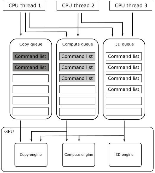
Many GPUs have one or more dedicated copy engines, a compute engine, and a 3D engine, each capable of executing specific commands in parallel with the other engines. For this reason, there can be no simple guarantee of the order of execution, hence the need for synchronization mechanisms that allow establishing an execution order, if needed.
For this sample, we will use a graphics command queue (referred to as the 3D queue in the illustration above) as it is capable of holding direct command lists that, in turn, can include all types of commands. Indeed, a graphics queue can drive all GPU engines; the compute queue can drive the compute and copy engines, and the copy queue can only drive the copy engine.
To create a swap chain, we need to specify the number of buffers, their size, format, and usage. We’re going to use two buffers of the same size as the window’s client area. That way, the buffers will be mapped to the client area without stretching the image.
DXGI_FORMAT_R8G8B8A8_UNORM indicates the format of the buffers. You can imagine the buffers in the swap chain as grids of (width * height) elements, whose common type is specified by a DXGI_FORMAT value. In this case, we indicate that each element is a 32-bit value composed of four 8-bit unsigned-normalized-integer channels, each in the range $[0/255, 255/255]=[0, 1]$ (that is, each channel can have 256 different values). The four channels are called R, G, B and A to mimic the RGB color model, where a color is defined by the amount of red, green and blue it includes. The channel A (called alpha) is used to control the transparency or the opacity of the color.
DXGI_USAGE_RENDER_TARGET_OUTPUT specifies that the buffers will be used as render targets (the targets of drawing operations executed by the GPU).
DXGI_SWAP_EFFECT_FLIP_DISCARD indicates that we want to use the flip presentation model (developed by Microsoft to provide a faster way to present frames on the screen) and that DXGI can discard the contents of a back buffer after it is presented to the user — this can enable some optimizations.
SampleDesc.Count specifies the number of samples per pixel. It should be always 1 as buffers presented using the flip presentation model don’t support multisampling (you need to explicitly create MSAA render targets and resolve yourself the results from multi samples to a single sample as part of the presentation of the frame; we will see how to implement MSAA in a later tutorial).
The call to CreateSwapChainForHwnd creates the swap chain. It takes the command queue, the window handle that describes where the buffers will be presented and the description of the buffers in the swap chain.
[!NOTE]
The comment in the source code states that the swap chain needs a queue to flush. That’s because, behind the scenes, the DXGI API creates a command list with the commands needed to create the buffers in the swap chain (in GPU memory).
Now, we have a pointer to IDXGISwapChain1. The corresponding COM object almost certainly also implements IDXGISwapChain3, so we get a pointer to this interface by using the member function ComPtr::As. IDXGISwapChain3 allows to invoke GetCurrentBackBufferIndex to get the index of the current back buffer in the swap chain (the buffer we are going to draw on; the render target).
The call to IDXGIFactory::MakeWindowAssociation disables the full screen transition when you press ALT+ENTER. We don’t need to provide support for such functionality in this sample.
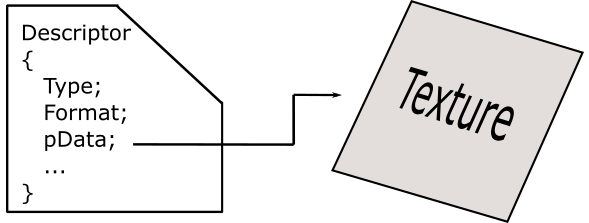
The next step is to create a descriptor heap, a memory space we can consider as an array of descriptors. A descriptor, as its name implies, it’s a block of data that describes a resource to the GPU (type, format, address and other hardware-specific information) for binding purposes. That is, whenever we need to bind a resource to the rendering pipeline, we pass a descriptor to the GPU to let it know where to find the resource and how to access it.

But why do we need to create a descriptor heap? Well, many GPUs require that binding information resides in a small size region of memory, which allows the GPU to use less bits to address them (for example, by using byte offsets from a base address). So, the primary purpose of a descriptor heap is to encompass the bulk of memory allocation required for storing descriptors.
Currently, we have a couple of buffers in the swap chain (allocated in GPU memory) that can be used as render targets. However, whenever we want to create a new frame, we need to bind one of them as render target so that the GPU exactly know where to draw. For this purpose, we need to create a descriptor for each buffer in the swap chain and record a binding command in the command list to specify the current render target to the GPU.
We will create descriptors and store them in a descriptor heap from our C++ applications. This means the descriptor heap needs to be CPU visible. That is, the related space must be allocated in CPU-visible video memory (a small part of dedicated VRAM) or in system memory (RAM). That’s exactly what CreateDescriptorHeap does.
[!NOTE]
If you are wondering how GPUs can access descriptors in system memory, the answer is that it is possible through the PCI-e bus. However, as for the descriptor of the render target, the GPU doesn’t even need to do that since the driver implicitly copies this descriptor in the command that binds the render target to the pipeline, so that the GPU can directly read from that command (in the correpsponding command list) the details about the buffer to use as render target.
[!NOTE]
Differently from render targets, descriptors for texture and other type of resources need to be accessed by the GPU wherever they are in memory. That is, the driver doesn’t copy the descriptors in the binding command (more on this in the next tutorial).
Then, we set the fields of a D3D12_DESCRIPTOR_HEAP_DESC structure to specify we want a descriptor heap that will hold two descriptors of type RTV (render target view; descriptor and view are pretty much the same thing in DirectX). That way, ID3D12Device::CreateDescriptorHeap creates a descriptor heap that has enough space to contain two RTVs, and returns an interface pointer to such descriptor heap in the last parameter (or more precisely, an interface pointer to the COM object that implements the interface we will use to reference the descriptor heap; I won’t stress on this point anymore).
Observe that a descriptor heap can only hold descriptors of a specific type. We will see other types of descriptors, and the related heaps, starting from the next tutorial.
ID3D12Device::GetDescriptorHandleIncrementSize returns the size of a descriptor, based on the type of descriptor heap passed as argument. In this case, we want to know the size of RTVs, so we pass a type of descriptor heap capable of containing them. We store this information for later use.
Once we have the descriptor heap, we need to create the views (RTVs) to the two buffers in the swap chain. ID3D12DescriptorHeap::GetCPUDescriptorHandleForHeapStart returns a CPU handle to the first descriptor in the heap, where we are going to store the first RTV.
[!NOTE]
As mentioned earlier, a descriptor heap must be CPU visible, so we need a CPU descriptor handle that points to a descriptor in a descriptor heap in order to store a view.
Handles are opaque pointers, meaning that a handle uniquely identifies a resource, but you shouldn’t dereference it as its value only makes sense within a specific context. However, as we will see later in this tutorial, in the context we are working in, CPU descriptor handles returned by GetCPUDescriptorHandleForHeapStart are simple CPU virtual addresses, allowing us to use pointer arithmetic to calculate the addresses of other descriptors (see the implementation of CD3DX12_CPU_DESCRIPTOR_HANDLE::Offset in d3dx12.h). This confirms that descriptor heaps are allocated in CPU-visible memory.
GPU descriptor handles also exist. However, we will only use them to reference descriptors in a special descriptor heap (more on this in the next tutorial). Observe that, unlike CPU handles, usually GPU handles are just byte offsets from the start of a descriptor heap, not virtual addresses.
[!NOTE]
CD3DX12_CPU_DESCRIPTOR_HANDLE is a wrapper for the Direct3D 12 structure CPU_DESCRIPTOR_HANDLE. In general, types with a name that begin with “CD3DX12” are defined in d3dx12.h and behave like C++ classes around Direct3D 12 structures to simplify their initialization and to provide useful helper functions.
IDXGISwapChain:: GetBuffer returns (as an output parameter) an interface pointer to the buffer of the swap chain associated with the index passed in the first parameter. In particular, we get a pointer to a ID3D12Resource interface, used to reference a wide variety of resources from our C++ application. That is, ID3D12Resource provides useful information about the related resource in GPU memory (type, format, dimension, GPU virtual address, etc.), but we cannot directly use it to access a GPU resource from CPU code.
[!NOTE]
ID3D12Resource is only an interface implemented by a COM object in system memory: it doesn’t directly reference resources in GPU memory. Even if you have the GPU virtual address of a resource, you can’t access it from your C++ application because it only “understands” addresses of its CPU virtual address space. However, in some cases, we can use ID3D12Resource to map the GPU memory space of a resource to the virtual address space of our application in order to make it CPU visible\accessible. More on this in the next tutorial.
With the pointers to the ID3D12Resource interfaces that describe the buffers in the swap chain, we can create the related views by calling ID3D12Device::CreateRenderTargetView, indicating the descriptor\position in the descriptor heap where we want to store them.
To get the handle of the second descriptor in the heap we use CD3DX12_CPU_DESCRIPTOR_HANDLE::Offset, which allows to offset a handle to point a different descriptor from the first one. For this purpose, we need to pass the number of descriptors to offset and their size. That’s the reason we stored the size of RTVs.
ID3D12Device:: CreateCommandAllocator creates a command allocator. This is essentially a memory manager for a command list, meaning it manages the memory space where a command list stores its commands. You must specify the type of command list the allocator is going to manage. A direct command list can hold all types of commands.
[!NOTE]
We’ll be recording commands in command lists from our C++ application, so the memory space managed by the allocators must be CPU visible. And indeed, the allocation occurs in memory accessible to both CPU and GPU. This implies that either of them can access the command list, although one of the two must do it through the PCI-e bus (further details will be covered in the next tutorial).
[!NOTE]
Be careful when reusing a command list because the CPU memory space holding the related commands might still be in use, accessed by the GPU. That is, we don’t know when the GPU finishes executing the commands of a command list, at least without a synchronization mechanism between CPU and GPU. We will see how to implement such a mechanism shortly.
Now, it’s time to look at the code of the LoadAssets function.
// Load the sample assets.
void D3D12HelloWindow::LoadAssets()
{
    // Create the command list.
    ThrowIfFailed(m_device->CreateCommandList(0, D3D12_COMMAND_LIST_TYPE_DIRECT, m_commandAllocator.Get(), nullptr, IID_PPV_ARGS(&m_commandList)));

    // Command lists are created in the recording state, but there is nothing
    // to record yet. The main loop expects it to be closed, so close it now.
    ThrowIfFailed(m_commandList->Close());

    // Create synchronization objects.
    {
        ThrowIfFailed(m_device->CreateFence(0, D3D12_FENCE_FLAG_NONE, IID_PPV_ARGS(&m_fence)));
        m_fenceValue = 1;

        // Create an event handle to use for frame synchronization.
        m_fenceEvent = CreateEvent(nullptr, FALSE, FALSE, nullptr);
        if (m_fenceEvent == nullptr)
        {
            ThrowIfFailed(HRESULT_FROM_WIN32(GetLastError()));
        }
    }
}
This function is responsible for creating other types of objects and resources that are needed to draw the frames of our graphics samples.
First, we create a direct command list using ID3D12Device::CreateCommandList, passing the related command allocator as an argument. A command list is initially created in a state where it is ready to receive commands. We have no commands to record in the list right now, though. Additionally, a command list must be closed when you call Reset on it. This is a common operation to perform the first time you use a command list or when you reuse it (often after submitting the command list to draw a previous frame). Therefore, we close the command list now, waiting to call Reset on it later.
ID3D12Device::CreateFence creates a fence. A fence is a synchronization object that you can insert in a command queue for synchronization purposes. Since a fence is a synchronization object that the GPU encounters during the execution of commands in command lists consumed from a command queue, we also need an event to notify a waiting CPU thread that the GPU reached a fence in the queue (more on this shortly).
At this point, the initialization stage (that is, the call to DXSample::OnInit in Win32Application::Run) is complete, and ShowWindow is invoked to activate the window and display it at its current size and position. Then, the application can enter the message loop, where PeekMessage retrieves a message from the message queue, and stores the related information in the MSG structure passed in the first parameter before returning TRUE (otherwise it returns FALSE to indicate no message was available). DispatchMessage dispatches a message to the window procedure. TranslateMessage translates virtual-key messages (WM_KEYDOWN, WM_KEYUP) into character messages (WM_CHAR) containing ASCII characters. This allows you to better distinguish the various keys on the keyboard.
However, remember that CreateWindow, before returning, sent a WM_CREATE message to the window procedure.
// Main message handler for the sample.
LRESULT CALLBACK Win32Application::WindowProc(HWND hWnd, UINT message, WPARAM wParam, LPARAM lParam)
{
    DXSample* pSample = reinterpret_cast<DXSample*>(GetWindowLongPtr(hWnd, GWLP_USERDATA));

    switch (message)
    {
    case WM_CREATE:
        {
            // Save the DXSample* passed in to CreateWindow.
            LPCREATESTRUCT pCreateStruct = reinterpret_cast<LPCREATESTRUCT>(lParam);
            SetWindowLongPtr(hWnd, GWLP_USERDATA, reinterpret_cast<LONG_PTR>(pCreateStruct->lpCreateParams));
        }
        return 0;

    case WM_KEYDOWN:
        if (pSample)
        {
            pSample->OnKeyDown(static_cast<UINT8>(wParam));
        }
        return 0;

    case WM_KEYUP:
        if (pSample)
        {
            pSample->OnKeyUp(static_cast<UINT8>(wParam));
        }
        return 0;

    case WM_PAINT:
        if (pSample)
        {
            pSample->OnUpdate();
            pSample->OnRender();
        }
        return 0;

    case WM_DESTROY:
        PostQuitMessage(0);
        return 0;
    }

    // Handle any messages the switch statement didn't.
    return DefWindowProc(hWnd, message, wParam, lParam);
}
Observe that we passed a pointer to the instance of the application class as the last parameter to CreateWindow. The operating system returns this pointer to us in response to a WM_CREATE message, giving us the opportunity to save it for later access. Inside the WM_CREATE message handler, lParam holds a pointer to CREATESTRUCT. The lpCreateParams field of this structure contains the last parameter passed to CreateWindow. We call SetWindowLongPtr to store this information in the user data associated with the window (an additional memory space reserved for the user) and we will retrieve it later using GetWindowLongPtr.
After the user closes the window, a WM_DESTROY message is sent to the window procedure of the destroyed window. The WM_DESTROY message handler invokes PostQuitMessage, which queues a WM_QUIT message. This enables us to exit the message loop in Win32Application::Run and execute DXSample::OnDestroy. This is a pure virtual function overridden by D3D12HelloWindow::OnDestroy. This function simply calls WaitForPreviousFrame, which waits for the GPU to complete rendering the previous frame (more on this shortly).
Typically, WM_PAINT messages are both sent to the window procedure and posted to the message queue throughout the application’s lifetime. This allows us to consistently call OnUpdate and OnRender within the WM_PAINT message handler. These are pure virtual functions overridden in D3D12HelloWindow. Since OnUpdate doesn’t perform any actions in this sample, let’s proceed directly to examining OnRender.
// Render the scene.
void D3D12HelloWindow::OnRender()
{
    // Record all the commands we need to render the scene into the command list.
    PopulateCommandList();

    // Execute the command list.
    ID3D12CommandList* ppCommandLists[] = { m_commandList.Get() };
    m_commandQueue->ExecuteCommandLists(_countof(ppCommandLists), ppCommandLists);

    // Present the frame.
    ThrowIfFailed(m_swapChain->Present(1, 0));

    WaitForPreviousFrame();
}
In PopulateCommandList, we record (into the command list) the commands required to render a frame. In this sample, we will simply paint the window’s client area blue. We’ll revisit this function shortly.
As we know, a command queue is a collection of command lists, so we can queue multiple command lists if needed. That’s why we pass an array of command lists to ID3D12CommandQueue::ExecuteCommandLists. This function submits the command lists (provided as an argument to the second parameter) to the command queue, making them ready for consumption by the GPU. The GPU start executing the command lists sequentially, preserving the order of submission. However, commands within command lists can be executed in parallel whenever possible.
At this point, it should be clear that we are dealing with two different timelines. The term “timeline” in this context refers to the time when something is executed. For example, creating a command queue, a command list, and a command allocator are operations executed on the CPU timeline because the creation of the related resources occurs at the time of an API call in our C++ application, which is executed by the CPU. Adding commands to a command list is also executed on the CPU timeline, but the execution of those commands belongs to the GPU timeline when the GPU actually consumes command lists from a command queue.
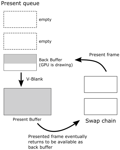
IDXGISwapChain::Present allows presenting the frame on the screen that was just created on the CPU timeline (using the current back buffer as the render target). How does it work? Present operations occur on the graphics queue associated with the swap chain. That is, when you call Present, a present operation is recorded in the command queue associated with swap chain during its creation, and a request to present the frame is inserted in a queue called the present queue, waiting for the GPU to execute the commands to draw on the related back buffer. Since this happens only after recording all the commands needed to create the frame, you are sure the GPU reached the present operation in the command queue only at the very end (i.e., after executing all the other previous drawing commands). At that point, the frame associated with the request in the present queue is done, ready to be shown on the screen at the next vertical interval when the swap/flip between the back and present buffers takes place.
[!IMPORTANT]
When you create a frame and present it on the CPU timeline, nothing happens on the related back buffer until the GPU starts executing drawing commands in the related command list.
Present also updates the index of the current back buffer in the swap chain so that the next frame will be created on the other buffer when it becomes available again as a render target.
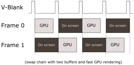
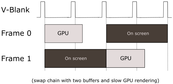
Observe that Present takes, as its first parameter (called SyncInterval), a value that specifies how to synchronize the presentation of a frame with the vertical blank. For values greater than zero, it indicates the number of vertical intervals the frame waits in the present queue before getting ready to be presented on the screen, enabling v-sync. In this sample, we always pass 1 as an argument to this parameter to specify that we want to wait a single vertical interval. In a later tutorial, we will explore what it means if you pass 0 to this parameter.
The term “vertical interval” (or vertical blank, depicted as a dashed diagonal line in the image below) refers to the time it takes for the scanning process to restart the refresh of your monitor.
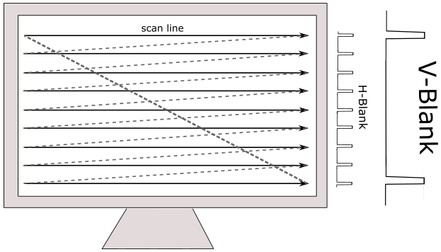
In the images below, you can observe that if the GPU isn’t able to draw on the render target quickly enough, the frames per second (FPS) can decrease by half. If a new frame is not prepared for presentation, the previous one will persist on the screen. That is, no swap occurs between back and front buffers at the next v-sync interval since the GPU has not finished drawing on the back buffer.
[!NOTE]
To be honest, the presentation of frames on the screen is a bit more intricate than I just explained. The outcome when presenting a frame can vary based on how you configure the swap chain, whether the window is in full-screen mode, or if v-sync is enabled. However, to avoid unnecessary complexity at this stage, we’ll revisit this topic in a later tutorial.
The sample examined in this tutorial uses a single command allocator to manage the memory space where drawing commands for both buffers in the swap chain are recorded. This implies that we need to flush the command queue before recording the commands to create and present a new frame, as all commands are recorded in the same memory space regardless of the frame we are creating — we can’t overwrite commands still in use by the GPU, obviously.
This way, CPU and GPU work sequentially: the CPU creates a frame and waits for the GPU to complete it. In other words, we still cannot create frames in advance on the CPU timeline compared to the GPU; in a later tutorial, we will explore how to unleash parallelism between CPU and GPU.
For this purpose, WaitForPreviousFrame waits for the GPU to finish executing the commands to compose the frame we just created and presented on the CPU timeline. However, before moving on to examine the code of WaitForPreviousFrame, we still need to review the implementation of the PopulateCommandList function.
void D3D12HelloWindow::PopulateCommandList()
{
    // Command list allocators can only be reset when the associated
    // command lists have finished execution on the GPU; apps should use
    // fences to determine GPU execution progress.
    ThrowIfFailed(m_commandAllocator->Reset());

    // However, when ExecuteCommandList() is called on a particular command
    // list, that command list can then be reset at any time and must be before
    // re-recording.
    ThrowIfFailed(m_commandList->Reset(m_commandAllocator.Get(), m_pipelineState.Get()));

    // Indicate that the back buffer will be used as a render target.
    m_commandList->ResourceBarrier(1, &CD3DX12_RESOURCE_BARRIER::Transition(m_renderTargets[m_frameIndex].Get(), D3D12_RESOURCE_STATE_PRESENT, D3D12_RESOURCE_STATE_RENDER_TARGET));

    CD3DX12_CPU_DESCRIPTOR_HANDLE rtvHandle(m_rtvHeap->GetCPUDescriptorHandleForHeapStart(), m_frameIndex, m_rtvDescriptorSize);

    // Record commands.
    const float clearColor[] = { 0.0f, 0.2f, 0.4f, 1.0f };
    m_commandList->ClearRenderTargetView(rtvHandle, clearColor, 0, nullptr);

    // Indicate that the back buffer will now be used to present.
    m_commandList->ResourceBarrier(1, &CD3DX12_RESOURCE_BARRIER::Transition(m_renderTargets[m_frameIndex].Get(), D3D12_RESOURCE_STATE_RENDER_TARGET, D3D12_RESOURCE_STATE_PRESENT));

    ThrowIfFailed(m_commandList->Close());
}
As mentioned above, a command allocator cannot be reused until the GPU has finished executing all the commands in the memory space managed by the allocator. Therefore, we need a fence to track the GPU progress. That’s exactly what WaitForPreviousFrame does at the end of OnRender. This way, we can be sure that whenever we call PopulateCommandexactlyList, we can reuse the command allocator.
On the other hand, we have no problems reusing the command list (associated with the same command allocator) after calling ExecuteCommandList, as we used a fence to ensure there are no pending commands. Thus, we can record new commands without worrying about overwriting pending commands in the memory space managed by the allocator. Alternatively, we can use the same command list but with a different command allocator. In any case, a command list must be reset every time we record new commands, and in turn, a reset needs a closed command list (which we did in LoadAssets).
ID3D12GraphicsCommandList::Reset takes the command allocator associated with the command list and, optionally, a pipeline state object (PSO) that sets the state of the rendering pipeline. In this case, m_pipelineState holds a null pointer that indicates to set a default pipeline state. We’ll return to the rendering pipeline and its state in the next tutorial.
Then, we indicate that we are going to use the current back buffer as the render target. We specify this information with a resource state transition. Why do we need to point out a state transition for a resource? Imagine having a buffer you use both for read and write operations. Before starting a read operation, all ongoing write operations need to be completed. State transitions are used to inform the GPU how we intend to use a resource so it can complete some ongoing operations on that resource before starting new ones.
The only rendering operation recorded for this first example involves cleaning the back buffer with an RGB color provided as an array of floats. In this case, the RGB color is $(0.0, 0.2, 0.4, 1.0)$, indicating a bluish tint assigned to each element of the back buffer. The last component is 1.0, which indicates a fully opaque color (no transparency).
Observe how we get a CPU handle to the RTV (Render Target View) of the current back buffer by offsetting the handle to the first RTV in the descriptor heap. For this purpose, we need the index of the current back buffer (m_frameIndex) and the size of an RTV (m_rtvDescriptorSize).
The images below demonstrate that, if you modify the code slightly and debug the sample, CPU descriptor handles are simple CPU virtual addresses, while GPU descriptor handles are offsets. Note that, in my case, m_ rtvDescriptorSize is 32 bytes (0x20 in hexadecimal), but remember that descriptors hold hardware-specific information, so this can vary from system to system.
if you change a bit the code and debug the sample, CPU descriptor handles are simple CPU virtual addresses, while GPU descriptor handles are offsets. Note that, in my case, m_ rtvDescriptorSize is 32 bytes (0x20 in hexadecimal), but remember that descriptors hold hardware-specific information, so this can vary from system to system.
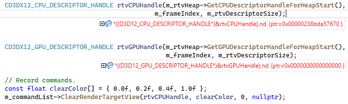
(First call to PopulatedCommandList)
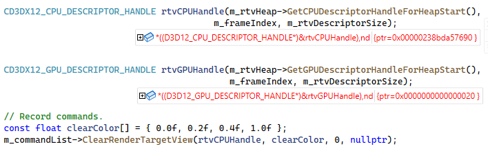
(Second call to PopulatedCommandList)
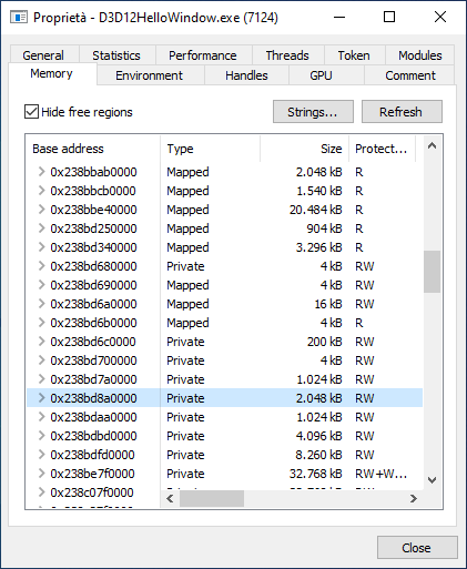
(Memory regions in the virtual address space of D3D12HelloWindow)
At this point, we have completed the frame creation on the CPU timeline, so we can modify the state of the back buffer to “present”. This indicates that, once this transition command is executed by the GPU, the back buffer is almost ready to be displayed on the screen (the GPU must first execute the corresponding present operation in the command queue).
Please remember that a command list must be closed before submitting it to the command queue.
Now, we can finally review the code of WaitForPreviousFrame, which is invoked at the end of OnRender. As previously mentioned, the primary purpose of this function is to flush the command queue.
void D3D12HelloWindow::WaitForPreviousFrame()
{
    // WAITING FOR THE FRAME TO COMPLETE BEFORE CONTINUING IS NOT BEST PRACTICE.
    // This is code implemented as such for simplicity. The D3D12HelloFrameBuffering
    // sample illustrates how to use fences for efficient resource usage and to
    // maximize GPU utilization.

    // Signal and increment the fence value.
    const UINT64 fence = m_fenceValue;
    ThrowIfFailed(m_commandQueue->Signal(m_fence.Get(), fence));
    m_fenceValue++;

    // Wait until the previous frame is finished.
    if (m_fence->GetCompletedValue() < fence)
    {
        ThrowIfFailed(m_fence->SetEventOnCompletion(fence, m_fenceEvent));
        WaitForSingleObject(m_fenceEvent, INFINITE);
    }

    m_frameIndex = m_swapChain->GetCurrentBackBufferIndex();
}
The comment at the beginning of the function states that you shouldn’t wait for a frame to complete. Indeed, we could start recording commands for the next frame if we had separated command allocators for the two buffers in the swap chain. Unfortunately, this is not the case, so we merely wait for the GPU to complete a frame before creating the next one on the CPU timeline. That way, we are sure the command queue is empty, so that we can reuse the command allocator whenever we call PopulateCommandList.
We store m_fenceValue in a local variable. Remember that the value of this member is 1 in the first call to WaitForPreviousFrame (look at the implementation of the LoadAssets function again).
ID3D12CommandQueue::Signal inserts in the command queue a fence with a value equal to the one passed as the second parameter (1, in this case). Then, we increase the value of m_fenceValue. At this point, in the command queue, there is the command list we submitted in OnRender, followed by a fence with value 1.
ID3D12Fence::GetCompletedValue returns the value of the last fence met\executed by the GPU in the command queue. If still no fence has been executed, this function returns 0. So, if the GPU hasn’t finished drawing the frame, we wait for m_fenceEvent to get signaled. Otherwise, if GetCompletedValue returns the fence value passed to Signal, we are sure that the GPU finished drawing the frame. A fence is signaled when the GPU meets\executes it on the command queue (that is, the execution of a fence results in a change from a non-signaled to a signaled state of the corresponding event associated with SetEventOnCompletion).
Observe that the call to IDXGISwapChain::Present, performed in OnRender before invoking WaitForPreviousFrame, updates the index of the current back buffer, so here GetCurrentBackBufferIndex returns the index of the buffer where to create the next frame. At that point m_fenceValue is 2, and a fence with this value will be used to delimit the command list submitted to the command queue to draw the second frame. And so on.
Source code: D3D12HelloWorld (DirectX-Graphics-Samples)
References
[1] About Windows (Microsoft Docs)
[2] Programming DirectX with COM (Microsoft Docs)
[3] DXGI overview (Microsoft Docs)
If you found the content of this tutorial somewhat useful or interesting, please consider supporting this project by clicking on the Sponsor button. Whether a small tip, a one time donation, or a recurring payment, it’s all welcome! Thank you!
